Powered by Blogger.
Showing posts with label electrical wiring. Show all posts

1963 Mercury V8 Monterey Wiring Diagrams #2

Saturday, March 5

This 1963 Mercury V8 Monterey Wiring Diagrams #2 Continuing the previous post about 1963 Mercury V8 Monterey Wiring Diagrams #1, Here you will be able to see many parts of diagrams you should understand. But you don't need to worry, because here we will provide you a very clear wiring diagram of  1963 Mercury V8 Monterey Wiring Diagrams #2  that very easy to read and understand.
In the wiring diagrams of 1963 Mercury V8 Monterey Wiring Diagramsyou will see parts like: courtesy light, glove box light & switch, clock & clock lights, heater light, ashtray light, cigar lighter, right direction indicator, windshield wiper switch connector, temperature gauge, etc.

For more detail, please see the 1963 Mercury V8 Monterey Wiring Diagrams below. You can click on the image to get larger image view.
Hopefully, this 1963 Mercury V8 Monterey Wiring Diagrams will give you benefits.
Please share if you care. Many thanks for sharing. :)
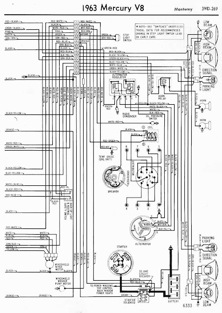
1963 Mercury V8 Monterey Wiring Diagrams #2

Read more...

1994 Mitsubishi Montero System wiring diagrams Heater Circuit

Monday, August 8

1994 Mitsubishi Montero System wiring diagrams Heater Circuit. This post is for the 1994 Mitsubishi Montero System wiring diagrams Heater Circuit. In this schematic wiring diagrams you will see the parts as: junction block, heat control illumination light, blower motor, blower motor relay, blower resistor, blower switch.
In this schematic wiring diagrams you will also see the wire color codes like: GRN = green, WHT = white, BLK = black, YEL = yellow, BLU = blue, RED = red, which make you easier in finding the wire.
So, be sure to understand the both parts before having your wiring works. For detail please see the image of the schematic wiring diagram below. You can click on the image to view in larger display.

1994 Mitsubishi Montero System wiring diagrams Heater Circuit
Hopefully this may help you in fixing your wire problems.
You may also see the other Mitshubishi Montero wiring diagrams HERE.

Read more...

1996 Mercedes-Benz C220 System Wiring Diagrams Headlight Circuit, W/ DRL

Wednesday, August 3

1996 Mercedes-Benz C220 System Wiring Diagrams Headlight Circuit, W/ DRL. This post will show you the components for the 1996 Mercedes-Benz C220 System Wiring Diagrams Headlight Circuit, W/ DRL. In this schematic wiring diagrams you are about to see the parts and components as listed thereafter:  terminal block, ignition switch, exterior lamp switch, fuse and relay box, daytime running lamp control module, combination switch, exterior lamp switch, exterior lamp failure monitoring module, left headlamp unit, fog lamp, right headlamp unit, instrument cluster. You are also about to see the wire color codes. Please, be sure to understand them all before you do your works.
Well, check this schematic wiring diagrams  to view the details.

1996 Mercedes-Benz C220 System Wiring Diagrams Headlight Circuit, W/ DRL


Read more...

1991 Mercedes-Benz 300E System Wiring Diagrams Anti-theft Circuit

Tuesday, August 2

This is for the 1991 Mercedes-Benz 300E System Wiring Diagrams Anti-theft Circuit. The content of this  schematic wiring diagrams are: auxiliary fuse holder, fuse relay box, alarm horn, exterior lights system, headlights system, anti-theft alarm control unit, trunk lamp switch, hood switch, convenience control unit beneath, right front door switch, left rear door switch, right rear door switch, anti-theft alarm connector, warning buzzer, connector block, stop lamp switch, right front door switch, left front door switch, supply pump, trunk lid lock actuator, right front door lock actuator, left front door actuator.
Pay attention also on the wire color codes, this will help you in determining the wire easily. Check this out, the  schematic wiring diagrams for the 1991 Mercedes-Benz 300E System Wiring Diagrams Anti-theft Circuit.
click on the image to enlarge

1991 Mercedes-Benz 300E Sytem Wiring Diagrams Anti-theft Circuit

Read more...

1997 Buick Regal System Wiring Diagrams Engine Performance Circuits

Wednesday, July 13

1997 Buick Regal System Wiring Diagrams Engine Performance Circuits
The content of the schematic wiring diagrams includes:

  • fuel pump relay
  • fuse block
  • instrument cluster : a set of instrumentation, including the speedometer, that is displayed with a digital readout rather than with the traditional analog gauges. (wikipedia)
  • exhaust gas recirculation valve: a vacuum controlled valve which allows a specific amount of your exhaust back into the intake manifold. (about.com)
  • throttle position sensor: a sensor used to monitor the position of the throttle in an internal combustion engine. (wikipedia)
  • engine coolant temperature sensor : a sensor that is screwed into the engine's block or cylinder head and is used to determine the temperature of the engine coolant. (obd-codes)
  • super charger bypass valve
  • stoplamp switch
  • underhood electrical center
  • fuel pump
  • fuel pump resistor
  • ignition amplifier and switching module
  • crankshaft position sensor
  • camshaft position sensor

Also pay attention on the wire color coding to ease you in determining each wire.
Click on the image to enlarge.
1997 Buick Regal System Wiring Diagrams Engine Performance Circuits

Read more...

Peugeot 206 Wiring Diagrams Central Locking

Sunday, July 10

Peugeot 206 Wiring Diagrams Central Locking
Here in you will see the Peugeot 206 Wiring Diagrams Central Locking. Central locking is a system by which all the doors of a motor vehicle can be locked simultaneously when the driver's door is locked (thefreedictionary). It is also known as electric door locks or Power door locks ) allow the driver or front passenger to simultaneously lock or unlock all the doors of an automobile or truck, by pressing a button or flipping a switch (wikipedia). In this schematic wiring diagrams of the Peugeot 206 Wiring Diagrams Central Locking, you will see the following parts:
  • Wire colors coding. These color coding let you know the color of each wire. It makes determining the wire much more easier. And among this wire colors are: BA White BE Blue, BG Beige, GR Grey, JN Yellow, MR Brown, NR Black, OR Orange, RG Red, RS Pink, VE Green, VI Mauve, VJ Green/Yellow.
  • Components/parts: Battery, Ignition switch,  Engine fusebox, Passenger fusebox (28 fuse), Built in systems interface (BSI),  LH front door lock motor assembly,  RH front door lock motor assembly,  LH rear door lock assembly,  RH rear door lock assembly, Boot/tailgate lock. You will also see the parts with these special marks like: * With rear power windows, ** Without rear power windows,  *** With deadlocking, **** Without deadlocking
To see the detail please observe the image below. click on image to enlarge. 

If you still not sure with your work, it is better for you to have an Insurance for your car. If you wanna buy new car but you can't afford it, Bank Loan may be the best coice. if you already have the new one it is good for you to do Charity by Donate Car for social purposes.
Peugeot 206 Wiring Diagrams Central Locking

Read more...

2003 Hyundai Santa Fe | System Wiring Diagrams | Radio Circuits

Saturday, July 9

2003 Hyundai Santa Fe | System Wiring Diagrams | Radio Circuits
As a Korean product, Hyundai has its own fanatic markets. They who decided to choose Hyundai as their vehicles must be known the plus and the minus point of Hyundai's cars.
One of the most adorn Hyundai car is the Hyundai Santa Fe. As a middle high SUV Santa Fe provides the costumers many comforts. But as other vehicle, Santa Fe also sometimes has its problems. One of the its problems is the Radio Circuits. So this post will try to show the wiring diagrams of the Santa Fe radio circuits, in order to provide information for those who need the information on it.
Well, when you see the 2003 Hyundai Santa Fe System Wiring Diagrams Radio Circuits image, you will see the parts as mentioned below:
passenger compartment junction block  
It is the components ,lies in the part of a vehicle where the passengers sit, used to supply electrical power to certain system in the vehicle.
audio head unit, amplifier speaker, left front speaker, right front speaker, left rear speaker, right rear speaker, right front tweeter speaker, left front tweeter speaker.
In the image, you are also going to notice the wire color coding, which makes you easier to determine each wire. So, see the image below and click the image to enlarge.

2003 Hyundai Santa Fe | System Wiring Diagrams | Radio Circuits
Wish you succeed on your wiring works. Cheers!!
 There is also available PREMIUM Hyundai Santa Fe 2001-2006 (Haynes Repair Manual) for your complete Guidance in repairing.

More Info : CLICK HERE

Where To Buy ?: CLICK HERE  

Latest Price : CLICK HERE

See Customers Review : CLICK HERE

Read more...

Peugeot 206 Wiring Diagrams Wash/wipe system, ABS

Wednesday, July 6

Peugeot 206 Wiring Diagrams Wash/wipe system, ABS.
On the previous post, we have discussed about the Peugeot 206 Wiring Diagrams Rear Windows, Heated Rear Window and Mirrors. Now let's continue to the next diagrams.
Wash/wipe system is a system operated by the same lever on the control stalk that operates the wipers, which directs a jet of water onto the windscreen and activates the wipers for a short period (cardictionary)
An anti-lock braking system (ABS, from German: Antiblockiersystem) is a safety system that allows the wheels on a motor vehicle to continue interacting tractively with the road surface as directed by driver steering inputs while braking, preventing the wheels from locking up (that is, ceasing rotation) and therefore avoiding skidding. (wikipedia)
In this schematic wiring diagrams of Peugeot 206 Wiring Diagrams Wash/wipe system, ABS, you will see the parts as follow:
the wire color coding: BA White
BE Blue, BG Beige, GR Grey, JN Yellow, MR Brown, NR Black, OR Orange, RG Red, RS Pink, VE Green, VI Mauve, VJ Green/Yellow. These wire color coding will make you easier to find the wires.
You are also about to see the parts/components of the Peugeot 206 Wiring Diagrams Wash/wipe system, ABS, such as: Battery, Ignition switch, Instrument cluster, control unit, ABS warning light, Engine fusebox, Passenger fusebox, Diagnostic connector, Built in systems interface (BSI), Stop light switch, Rain sensor (if fitted), Front wiper motor, Rear wiper motor, washer pump, Wash/wipe switch, horn switch (not used), rear wiper switch, washer switch, Wash/wipe switch (continued), front wiper switch, ABS control unit, LH rear wheel sensor, RH rear wheel sensor, LH front wheel sensor, RH front wheel sensor.
More, you will see some parts marked with these signs: * With rear power windows, ** Without rear power windows.
Please observe the image for details. click on image to multiple enlarge.

If you still not sure with your work, it is better for you to have an Insurance for your car. If you wanna buy new car but you can't afford it, Bank Loan may be the best coice. if you already have the new one it is good for you to do Charity by Donate Car for social purposes.
Peugeot 206 Wiring Diagrams Wash/wipe system, ABS.

Read more...

1997 Ford Windstar System Wiring Diagrams Anti-lock Brake Circuits

Tuesday, July 5

This post continues the previous on Air Conditioning Circuits. In this post you will see the parts of the 1997 Ford Windstar System Wiring Diagrams Anti-lock Brake Circuits.
You will about to see these following parts on the schematic wiring diagrams shown in image.They are: engine compartment fuse box, auxiliary warning module, Brake on/off switch, instrument cluster, brake indicator, anti-lock brake indicator, left front wheel speed sensor, left rear wheel speed sensor, right rear wheel speed sensor, right front wheel speed sensor, anti-lock brake control module, generic electronic module, daytime running lights, park brake switch, brake pressure switch, brake fluid level switch, ignition switch.
You are also about to see the wire color coding that lets you know the each wire in different colors. Pay attention on it in order to make your work easier. 

To see the image Click here

Read more...

1997 Ford Windstar System Wiring Diagrams Air Conditioning Circuits

Friday, July 1

1997 Ford Windstar
The Ford Windstar is a minivan that was produced and sold by the Ford Motor Company from the 1995 to 2003 model years [wikipedia]. This car became very popular because of its design that suit for a family car. Year after year it gained the great sales. This became the adorable minivan at that time. No wonder till now there are many people still keeping it.


But this mini car was not free from the problems. As an old car it must be for sure to have some problems, especially with its electricity wiring system. So this post will give a glance for the 1997 Ford Windstar System Wiring Diagrams Air Conditioning Circuits.
In this schematic wiring diagrams you will see some parts namely: aux blower motor relay, blend door actuator, temperature control potentiometer, i/p fuse panel, aux blower motor, a/c clutch cycling pressure switch, blower motor, front blower motor, aux blower motor resistor assembly, aux a/c relay, blower motor switch, blower motor resistor, rear aux blower motor switch, front aux blower motor switch, engine compartment fuse box, a/c high pressure cutout/fan switch, pcm power relay, cooling fan dropping resistor, constant control relay module, a/c clutch control, left electric cooling fan motor, right electric cooling fan motor, a/c clutch coil, power train control module.
You are also about to see the wire color coding: WHT= white, PNK= pink, BLK= black, ORG= orange, RED= red, PPL= purple, BLU= blue, DK BLU= dark blue, GRN= green, LT GRN= light green, etc. 
You can see the details image/picture of the 1997 Ford Windstar System Wiring Diagrams Air Conditioning Circuits  HERE.

Read more...

1999 Ford Taurus SE System Wiring Diagrams Radio Circuits, W/ Cassette Deck

Tuesday, June 28

1999 Ford Taurus SE System Wiring Diagrams Radio Circuits, W/ Cassette Deck
The content of this schematic wiring diagram:
fuse junction panel, ground illumination, audio system on, fused ignition, heated mirror, integrated control panel, right rear speaker, right front door sail speaker, right front door speaker, left rear speaker, left front door sail speaker, battery junction box, rear control unit, CD changer. 
Those are the parts you should understand before having a wiring work on your 1999 Ford Taurus SE System Wiring Diagrams Radio Circuits, W/ Cassette Deck. After that, you should consider the wire color coding.  It can be seen in the schematic wiring diagram image below.
And you are ready to work on your 1999 Ford Taurus SE System Wiring Diagrams Radio Circuits, W/ Cassette Deck, after you have understood the thing I have mentioned above.

click on image to enlarge.

1999 Ford Taurus SE System Wiring Diagrams Radio Circuits, W/ Cassette Deck

Read more...

Peugeot 206 Wiring Diagrams Rear Windows, Heated Rear Window and Mirrors

Friday, June 24

Peugeot 206 Wiring Diagrams Rear Windows, Heated Rear Window and Mirrors
Continuing the previous posts, here I got the Peugeot 206 Wiring Diagrams Rear Windows, Heated Rear Window and Mirrors. In this schematic wiring diagrams you will see:
Battery, Ignition switch, Engine fusebox, Passenger fusebox (28 fuse), Starter motor, Alternator, Built in systems interface (BSI), Passenger's mirror assembly, Mirror and window control switch, Driver's mirror assembly, Rear function locking relay, Rear window isolator switch, LH rear window switch, LH rear window motor, RH rear window switch, RH rear window motor, Heated rear window, Heater panel.
You will also see the wire color coding: BA White
BE Blue, BG Beige, GR Grey, JN Yellow, MR Brown, NR Black, OR Orange, RG Red, RS Pink, VE Green, VI Mauve, VJ Green/Yellow.
Please do understand those parts and wire color coding in order to get successful works. And for the details please see the clear, colorful, and readable schematic wiring diagrams image below. Click on it to enlarge.

Read more...

2002-2004 Holden VY Commodore 3.8 Ltr Supercharged V6 Engine Management Wiring Diagram 1

Responding the emails requesting Schematic wiring diagram on Holden Commodore, so here I provide the 2002-2004 Holden VY Commodore 3.8L Supercharged V6. In this schematic wiring diagrams you will see the parts namely: Auto Transmission, Fuel Injectors, A/C Pressure Switch, Starter Motor, A/C Clutch Relay, Boost Control Solenoid, MAP Sensor, Vehicle Speed Sensor, Knock Sensors, Ignition Switch, Oil Pressure Switch, Fuel Pump Module, Fuel Pump Relay.
You will also see the Wire Color Legend. It shows the wire color coding such as: black-B, brown-BR, green-G, gray-GR, blue-L, light brown-LB, light green-LG, pink-P, red-R, sky blue-SB, orange-O, violet-V, white-W, yellow-Y, silver-SI.
Be sure to notice the parts and the wire color coding. By doing so you will be able to do your wiring works easily. For more details please observe this clear and readable image below. Click on it to enlarge.
2002-2004 Holden VY Commodore 3.8 Ltr Supercharged V6  Engine Management Wiring Diagram 1

Read more...

2002 Acura 3.2TL System Wiring Diagrams part 1

Thursday, June 23

Responding to the emails coming in the last few days, here I provide the first of the five series for the 2002 Acura 3.2TL System Wiring Diagrams. Based on the request by emails for the Acura wiring diagrams please see the schematic wiring diagrams attached below. Due to the limit of time I will provide the 2002 Acura 3.2TL for the first. It is the SYstem Wiring Diagrams. The diagram itself actually consists of 5 part, but here I will give one by one. The detail of the 2002 Acura 3.2TL System Wiring Diagrams are as follow:
The parts shown in this schematic wiring diagram: engine coolant temperature gauge, tachometer, speedometer, odometer/trip/ outside air temperature display, fuel gauge, indicator circuit, srs indicator light, wiper washer indicator light, maintenance required indicator light, low fuel indicator light, abs indicator light, vsa system indicator light, turn signal lights indicators, VSA activation indicator light, charging system indicator light, brake system indicator light, side airbag indicator light, seatbelt reminder light, driver underdash box, transmission range switch, shift lever detent racket assembly, powertrain control module, driver's underdash fuse relay box, passenger's underdash fuse relay.
Beside the parts above, there are color codes. And luckily the image provided here is drawn in color, so you are easy to differentiate one and another wire.
And after knowing the parts and the color codes, you are now ready to work on this wiring. For detail please see the image below. Click on it to enlarge.

2002 Acura 3.2TL System Wiring Diagrams 1

Read more...

Peugeot 206 Schematic Wiring Diagrams Audio System, Electric Windows

Wednesday, June 22

I've got emails requesting the Peugeot 206 wiring diagrams. Most them had got clear info from the previous posts and want for more. So, I would like to provide more and more schematic wiring diagrams as the feedback of the appreciation  to those who get a lot of information in this Blog.
So let's discuss for the Peugeot 206 Schematic Wiring Diagrams Audio System, Electric Windows. It is specialized for those who have problem with audio system and electric window in their Peugeot 206. For your information, there are some parts in this schematic wiring diagrams. It is a must to understand them before taking action on the wiring works. In this schematic wiring diagrams the parts are shown in Keys to show each items. Please take a look this list:
Key to items: 1 Battery, 2 Ignition switch, 4 Engine fusebox, 5 Passenger fusebox (28 fuse), 9 Built in systems interface (BSI), 100 Audio unit (2040 model), 101 Satellite controls, 102 Electric aerial module, 103 LH rear speaker, 104 LH tweeter, 105 Passenger's front door speaker, 106 RH rear speaker, 107 RH tweeter, 108 Driver's front door speaker, 113 CD player, 114 Multifunction display unit, 115 Passenger's mirror assembly, 116 Window and mirror control switch, 117 One-touch control unit, 118 Driver's window motor, 119 Passenger's window motor.
You also need to consider the wire color codes, and here is the list of wire colors codes: BA White, BE Blue, BG Beige, GR Grey, JN Yellow, MR Brown, NR Black, OR Orange, RG Red, RS Pink, VE Green, VI Mauve, VJ Green/yellow.
Well after you understand the codes above you will be able to solve your wiring problem. Be sure that you make no mistakes, failures, and errors. The clear, readable and colorful schematic wiring diagrams will be shown below. Just click on image to enlarge.
Peugeot 206 Schematic Wiring Diagrams Audio System, Electric Windows
If you still not sure with your work, it is better for you to have an Insurance for your car. If you wanna buy new car but you can't afford it, Bank Loan may be the best coice. if you already have the new one it is good for you to do Charity by Donate Car for social purposes.


Read more...

The 1995 Chevrolet Tahoe Wiring Schematic Anti-lock Brake Circuits

Monday, June 20

In this wiring schematic you will see the The 1995 Chevrolet Tahoe Wiring Schematic Anti-lock Brake Circuits. This is the series of the The 1995 Chevrolet Tahoe Wiring Schematics which will be uploaded soon. Well, lets elaborate the The 1995 Chevrolet Tahoe Wiring Schematic Anti-lock Brake Circuits. Here you can see the detail information concerning with this wiring schematics. My suggestion is that you should understand the parts first before you do the wiring works. And you can see the parts as the list below:
underhood fuse relay center, fuse block (brake fuse, gauge fuse), convenience center, data link connector, tcc/stoplamp and cruise switch (on brake pedal support arm), brake pressure modulator valve (left front of cowl on brake master cylinder), left front wheel sensor, right front wheel sensor, anti-lock indicator, brake indicator, instrument cluster (i/p), diode (behind left side of i/p), vehicle speed sensor buffer(behind i/p on the right side of steering column), brake pressure warning lamp warning(on master brake cylinder). 
The next you have to understand is the color codes. It is written in the image. It symbolize colors of the wires, so you will be easy to find them. Among those are: RED= red, BLK= black, BRN= brown, PNK= pink, WHT= white, LT BLU= light blue, DK GRN= dark green, PPL= purple, etc.
Well, after you understand the both, color codes and the parts, you are now ready to proceed to the wiring works. Be sure to make no mistakes and failures to get the best result. To more details you may see the vivid, clear and readable image below. Click on it to enlarge.


The 1995 Chevrolet Tahoe Wiring Schematic Anti-lock Brake Circuits
Hopefully, this schematic wiring diagrams  can help and solve your problems.

Read more...

Peugeot 206 System Wiring Diagrams Clock, Cigar Lighter, Sunroof, Audio System

Saturday, June 18

Herein the schematic wiring diagram I'd like to discuss is about the Peugeot 206 System Wiring Diagrams Clock, cigar lighter, sunroof, audio system. Here you will see the parts building the wiring system. You will see the parts as the following list:
1 Battery, 2 Ignition switch, 4 Engine fusebox, 5 Passenger fusebox (28 fuse), 9 Built in systems interface (BSI), 98 Cigar lighter, 99 Clock, 100 Audio unit (2030 model), 101 Satellite controls, 102 Electric aerial module, 103 LH rear speaker, 104 LH tweeter, 105 Passenger's front door speaker, 106 RH rear speaker, 107 RH tweeter, 108 Driver's front door speaker, 109 Sunroof assembly.
Beside the parts you have seen above you will also see the wire color codes. It is shown to ease you seeing the exact wire you are going to do with. And among the wire color codes you can see the list below:
Wire colours: BA White, BE Blue, BG Beige, GR Grey, JN Yellow, MR Brown, NR Black, OR Orange, RG Red, RS Pink, VE Green, VI Mauve, VJ Green/Yellow.
  • Note for the Cigar Lighter: Note fuse 23 may be supplied directly from battery or via ignition switch.
  • Note for Audio unit - 2030 model: Note fuse 24 may be supplied directly from battery or via ignition switch.
After noticing the whole description on Peugeot 206 System Wiring Diagrams Clock, cigar lighter, sunroof, audio system, hopefully, you will be able to do your work successfully. Here the vivid and readable color schematic wiring diagrams for the Peugeot 206 System Wiring Diagrams Clock, cigar lighter, sunroof, audio system. Click on the image to enlarge. Or using picasa photo viewer for best view.
Peugeot 206 System Wiring Diagrams Clock, Cigar Lighter, Sunroof, Audio System

Read more...

This is the 1995 Chevrolet Tahoe System Wiring Diagrams Heater Circuit

Friday, June 17

This is the 1995 Chevrolet Tahoe System Wiring Diagrams Heater Circuit
In this part of Wiring diagrams, you will see the parts as follow:
underhood fuse relay center, fuse block, blower switcher, blower resistor, high blower relay, blower motor.
This is very simple but still have to get enough attention for the best result. Please notice the color codes as well. And after you understand both, it is guaranteed that you will success on you wiring work. 
Here is the image. Click on it to enlarge.

This is the 1995 Chevrolet Tahoe System Wiring Diagrams Heater Circuit

Read more...

1995 Chevrolet Tahoe System Wiring Diagrams Air Conditioning Circuits

Thursday, June 16

In this 1995 Chevrolet Tahoe System Wiring Diagrams Air Conditioning Circuits, you will see the parts as follow:
underhood fuse-relay, fuse block, underhood fuse-relay center, water valve, a/c low pressure cutout switch, a/c compressor clutch relay, heater and a/c control module, a/c high pressure cutout switch, blower resistor, powertrain control module, high blower relay, auxiliary cooling fan motor, auxiliary cooling fan relay, blower motor, auxiliary cooling fan a/c pressure switch, mode door actuator, temperature door actuator, auxiliary cooling fan temperature switch.
Beside seeing the list of the components above, you will also see the coloring codes of the schematic wiring diagrams. After understanding the both, parts and coloring codes, you are now ready with your wiring works. Please ensure to minimize of doing mistakes and errors to get best result.
Here is the clear and readable image you can see as the guide for your works. Just click it on the image to enlarge or view it using picasa photo viewer for the best result.
1995 Chevrolet Tahoe System Wiring Diagrams Air Conditioning Circuits

Read more...

Peugeot 206 Wiring Schematic Interior lighting continued, headlight leveling.

Tuesday, June 14

Here is the Peugeot 206 Wiring Schematic Interior lighting continued, headlight leveling. In this schematic wiring diagrams will be shown the things that you have to understand before you have any wiring works on your Peugeot 206. They includes the wire color codes and the Key to items. The following lists will show you the brief description on them. Pay attention on them.
Wire colors:
BA=White, BE=Blue, BG=Beige, GR=Grey, JN=Yellow, MR=Brown, NR=Black, OR=Orange, RG=Red, RS=Pink, VE=Green, VI=Mauve, VJ=Green/Yellow.

Key to items
1. Battery, 2. Ignition switch, 4. Engine fusebox, 5. Passenger fusebox (28 fuse), 9. Built in systems interface (BSI), 68. Multifunction switch, a = side/headlight switch, 80. LH front door contact switch, 81. RH front door contact switch, 82. LH front door lock assembly, 83. RH front door lock assembly, 87. Interior light, 88. Map reading light, 89. Luggage compartment light, 90. Luggage compartment light switch, 91. Glove box light, 92. Glove box light switch, 93. Headlight leveling control switch, 94. LH headlight leveling motor, 95. RH headlight leveling motor.

Below is the clear and readable colorful schematic wiring diagrams for the Peugeot 206's Interior lighting continued, headlight leveling. Just click on the image to enlarge, or using the picasa photo viewer for the best result.


Peugeot 206 Wiring Schematic Interior lighting continued, headlight leveling.

Read more...

  © Blogger templates Newspaper by Ourblogtemplates.com 2008

Back to TOP